L293d Continuity Between Vss and Ground
In this tutorial, we will see L293d Motor Driver Working Operation.
You can also read 8051 DC Motor interfacing, PIC16F877A DC motor interfacing, LPC2148 DC motor interfacing, Bluetooth interfacing with PIC16F877A, and Bluetooth interfacing with 8051.
Introduction
Even the simplest robot requires a motor to rotate a wheel or performs particular action. Since motors require more current than the microcontroller pin can typically generate, you need some type of a switch that can accept a small current, amplify it and generate a larger current, which further drives a motor. This entire process is done by what is known as a Motor driver. With L293D Motor Driver IC, that task is made simple and has helped in a number of applications with relative ease.
L293D H-bridge driver is the most commonly used driver for Bidirectional motor driving applications. This L293D IC allows DC motor to drive on either direction. L293D is a 16-pin IC which can control a set of two DC motors simultaneously in any direction. It means that you can control two DC motor with a single L293D IC. Because it has two H-Bridge Circuit inside. The L293D can drive small and quiet big motors as well. There are various ways of making an H-bridge motor control circuit such as using transistors, relays, and using L293D/L298. Before going into detail, first we will see what is H-Bridge circuit.
H-Bridge Circuit Working (L293D Motor Driver Working)
A motor driver is basically a current amplifier which takes a low-current signal from the microcontroller and gives out a proportionally higher current signal which can control and drive a motor. In most cases, a transistor can act as a switch and perform this task which drives the motor in a single direction.
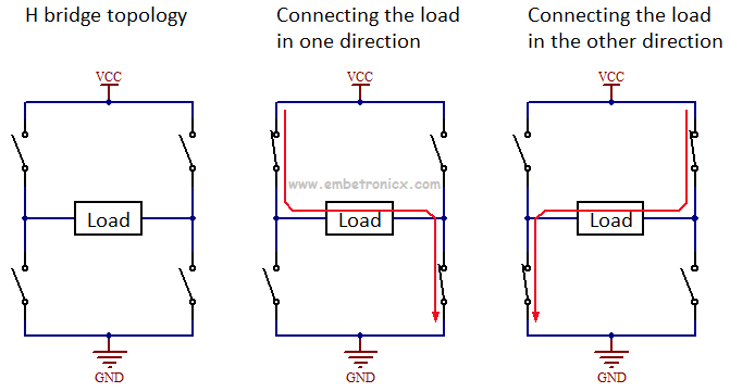
Turning a motor ON and OFF requires only one switch to control a single motor in a single direction. What if you want your motor to reverse its direction? The simple answer is to reverse its polarity. This can be achieved by using four switches that are arranged in an intelligent manner such that the circuit not only drives the motor but also controls its direction. Out of many, one of the most common and clever designs is an H-bridge circuit where transistors are arranged in a shape that resembles the English alphabet "H".
A H bridge is an electronic circuit that allows a voltage to be applied across a load in any direction. H-bridge circuits are frequently used in robotics and many other applications to allow DC motors to run forward & backward. These motor control circuits are mostly used in different converters like DC-DC, DC-AC, AC-AC converters, and many other types of power electronic converters. In specific, a bipolar stepper motor is always driven by a motor controller having two H-bridges.
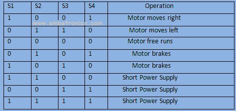
A H-bridge is fabricated with four switches like S1, S2, S3 and S4. When the S1 and S4 switches are closed, then a +ve voltage will be applied across the motor. By opening the switches S1 and S4 and closing the switches S2 and S3, this voltage is inverted, allowing invert operation of the motor.
Generally, the H-bridge motor driver circuit is used to reverse the direction of the motor and also to brake the motor. When the motor comes to a sudden stop, as the terminals of the motor's are shorted. Or let the motor run free to a stop when the motor is detached from the circuit. The table below gives the different operations with the four switches corresponding to the above circuit.
L293D IC
L293D IC generally comes as a standard 16-pin DIP (dual-in line package). This motor driver IC can simultaneously control two small motors in either direction; forward and reverse with just 4 microcontroller pins (if you do not use enable pins).
PIN Diagram
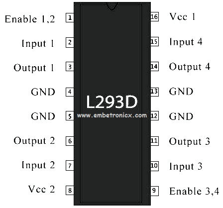
Pin Description
| PIN No | PIN NAME | Description |
|---|---|---|
| 1 | ENABLE 1 | When the enable pin is high, then the left part of the IC will work otherwise it won't work. This pin is also called as a master control pin of left side. |
| 2 | INPUT 1 | When the input pin is high, then the flow of current will be through output 1 |
| 3 | OUTPUT 1 | This output-1 pin must be connected to one of the terminals of the motor |
| 4 | GND | Connected to Ground |
| 5 | GND | Connected to Ground |
| 6 | OUTPUT 2 | This pin must be connected to one of the terminals of the motor |
| 7 | INPUT 2 | When this pin is HIGH then the flow of current will be though output 2 |
| 8 | VS | This is the voltage pin which is used to supply the voltage to the motor (12v) |
| 9 | ENABLE 2 | When this pin is high, then the right part of the IC will work & when it is low the right part of the IC won't work. This pin is also called as a master control pin for the right part of the IC. |
| 10 | INPUT 3 | When this pin is high, then the flow of current will through output-3 |
| 11 | OUTPUT 3 | This pin must be connected to one of the terminals of the motor |
| 12 | GND | Connected to Ground |
| 13 | GND | Connected to Ground |
| 14 | OUTPUT 4 | This pin must be connected to one of the terminals of the motor |
| 15 | INPUT 4 | When this pin is high, then the flow of current will be through output-4 |
| 16 | VSS | This pin is the power source to the integrated circuit (5v) |
Connection Diagram
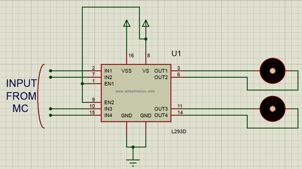
The circuit shown to the right is the most basic implementation of L293D IC. There are 16 pins sticking out of this IC and we have to understand the functionality of each pin before implementing this in a circuit.
-
Pin1 and Pin9 are "Enable" pins. They should be connected to +5V for the drivers to function. If they pulled low (GND), then the outputs will be turned off regardless of the input states, stopping the motors. If you have two spare pins in your microcontroller, connect these pins to the microcontroller, or just connect them to regulated positive 5 Volts.
-
Pin4, Pin5, Pin12, and Pin13 are ground pins that should ideally be connected to the microcontroller's ground.
-
Pin2, Pin7, Pin10 and Pin15 are logic input pins. These are control pins which should be connected to microcontroller pins. Pin2 and Pin7 control the first motor (left); Pin10 and Pin15 control the second motor(right).
-
Pin3, Pin6, Pin11, and Pin14 are output pins. Tie Pin3 and Pin6 to the first motor, Pin11 and Pin14 to second motor
-
Pin16 powers the IC and it should be connected to regulated +5Volts
-
Pin8 powers the two motors and should be connected to positive lead of a secondary battery. As per the datasheet, supply voltage can be as high as 36 Volts.
I have shown you where to connect the motors, battery and the microcontroller. But how do we control the direction of these motors? Let us take an example:
Suppose you need to control the left motor which is connected to Pin3 (O1) and Pin6 (O2). As mentioned above, we require three pins to control this motor – Pin1 (E1), Pin2 (I1) and Pin7 (I2). Here is the truth table representing the functionality of this motor driver.
| ENABLE 1 | INPUT 1 | INPUT2 | FUNCTION |
|---|---|---|---|
| 1 | 1 | 0 | Rotates Anti-clockwise (Reverse) |
| 1 | 0 | 1 | Rotates Clockwise (Forward) |
| 1 | 1 | 1 | OFF |
| 1 | 0 | 0 | OFF |
| 0 | X | X | OFF |
X= Either high or low (don't care)
In the above truth table, you can observe that if ENABLE 1 is low then the motor stops, irrespective of the states on INPUT 1 and INPUT 2. Hence it is essential to hold ENABLE 1 high for the driver to function, or simply connect enable pins to positive 5 volts.
With ENABLE 1 high, if INPUT 1 is set high and INPUT 2 is pulled low, then current flows from INPUT 1 to INPUT 2 driving the motor in anti-clockwise direction. If the states of INPUT 1 and INPUT 2 are flipped, then current flows from INPUT 2 to INPUT 1 driving the motor in a clockwise direction.
The above concept holds true for other side of the IC too. Connect your motor to OUTPUT 3 and OUTPUT 4; INPUT 3 and INPUT 4 are input pins and ENABLE 2 enables the driver.
You can find the Datasheet Here.
You can also read the below tutorials.
| Linux Device Driver Tutorials | C Programming Tutorials |
| FreeRTOS Tutorials | NuttX RTOS Tutorials |
| RTX RTOS Tutorials | Interrupts Basics |
| I2C Protocol – Part 1 (Basics) | I2C Protocol – Part 2 (Advanced Topics) |
| STM32 Tutorials | LPC2148 (ARM7) Tutorials |
| PIC16F877A Tutorials | 8051 Tutorials |
| Unit Testing in C Tutorials | ESP32-IDF Tutorials |
| Raspberry Pi Tutorials | Embedded Interview Topics |
| Reset Sequence in ARM Cortex-M4 | BLE Basics |
| VIC and NVIC in ARM | SPI – Serial Peripheral Interface Protocol |
| Bootloader Tutorials | Raspberry PI Pico Tutorials |
| Zephyr RTOS Tutorials - STM32 | Zephyr RTOS Tutorials - ESP32 |
| VHDL Tutorials | UDS Protocol Tutorials |
| Product Reviews |
Embedded Software | Firmware | Linux Devic Deriver | RTOS
Source: https://embetronicx.com/tutorials/tech_devices/l293d-motor-driver-working/
0 Response to "L293d Continuity Between Vss and Ground"
Post a Comment